Fused Silica–Epoxy at 9.5 GHz: How to Compare Dielectric-Loss Claims
Interpret fused silica–epoxy dielectric loss at 9.5 GHz using the published unfilled control, specimen equivalence, metric definition and laboratory uncertainty.
Industrial application guide · Technical review ·
Fused Silica–Epoxy at 9.5 GHz: How to Compare Dielectric-Loss Claims
A low-loss number is useful only when its frequency, material control and measurement definition are clear. For fused-silica–epoxy buyers, a published microwave comparison is a starting point for test planning, not a transferable finished-laminate specification.
What the published evidence establishes
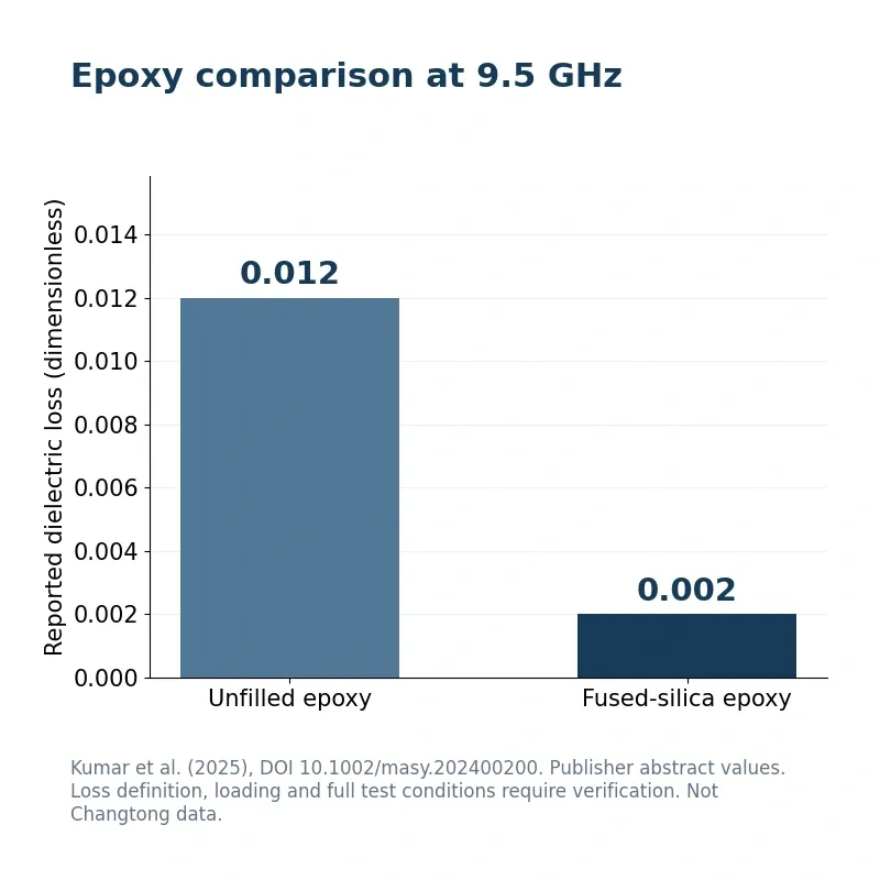
Kumar, Gupta and Rajauriya report a fused-silica–epoxy composite with dielectric loss of 0.002 at 9.5 GHz, compared with 0.012 for unfilled epoxy. The reported relative dielectric constant was approximately 2.5 and remained close to the unfilled reference. These values come from the publisher-indexed abstract. The accessible evidence does not establish filler loading, specimen preparation, temperature, uncertainty or a verified measurement fixture for reproducing the result. [1]
Define what the loss number means
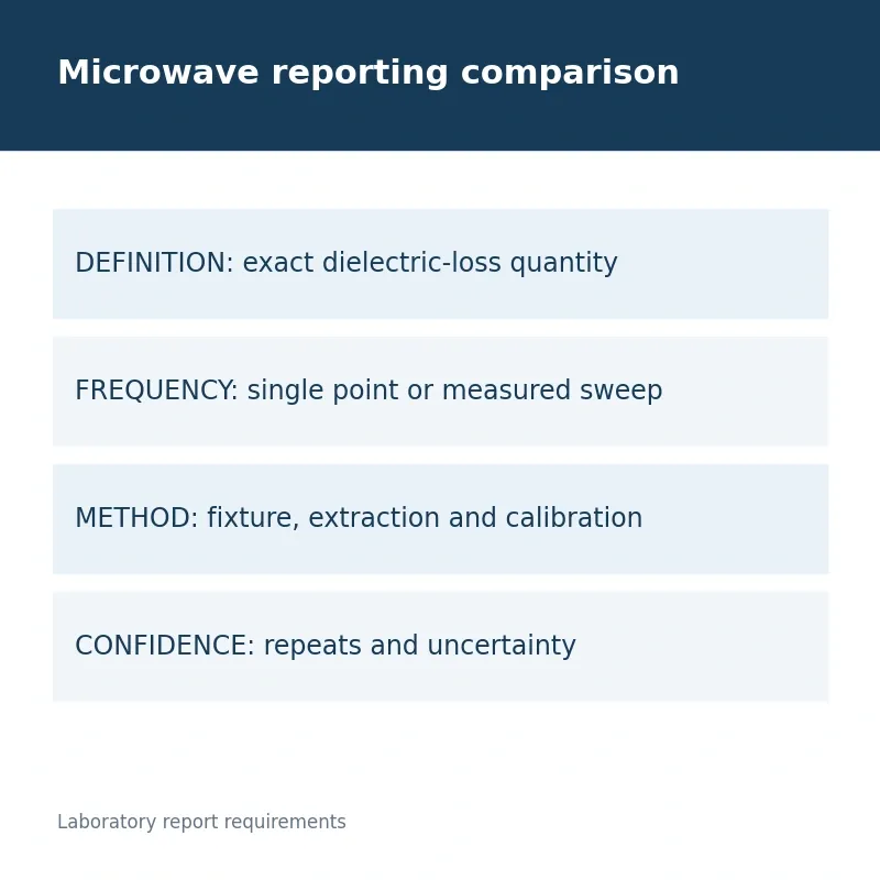
Ask the laboratory to identify the reported dielectric quantity, its units or dimensionless convention, extraction model and test method. Do not automatically rename a loosely labeled dielectric-loss result as loss tangent without verifying the paper or laboratory definition. Record the operating frequency and any frequency sweep. A single-point result should stay associated with that point, rather than becoming a broadband product claim.
Match the specimen before comparing instruments
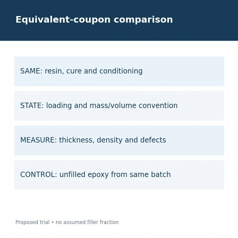
Prepare unfilled and filled coupons with the same resin batch, cure and conditioning history. Record filler fraction and its mass or volume basis, thickness, density and visible defects. Void content or incomplete cure can confound a comparison. If two laboratories disagree, first check whether they received equivalent specimens and used equivalent quantities and conditioning; instrument brand alone will not explain the difference.
Document the measurement and uncertainty
Include fixture or resonator identification, calibration, specimen fit, temperature and repeat measurements in the test report. Request the method’s uncertainty or repeatability information when a result is close to the acceptance target. The article does not assign a specific fixture to the cited study because that detail was not verified. The customer laboratory should select a method suitable for its specimen and frequency range.
| Comparison | Record to retain | Decision use |
|---|---|---|
| Definition | Dielectric quantity, extraction and reporting convention | Do not silently equate unlike loss metrics |
| Specimen | Loading basis, cure, thickness, density and conditioning | Keep the unfilled control comparable |
| Measurement | Frequency, fixture, calibration and uncertainty | Make a near-target result interpretable |
Keep composite evidence separate from laminate evidence
The reported sample was a powder-filled epoxy composite. A copper-clad laminate adds glass reinforcement, copper interfaces and a press history, while a potting component has its own geometry and moisture exposure. Use the composite comparison to decide what to measure next. Qualify the final article at the customer’s operating conditions before approving any claim about signal loss, insulation or reliability.
Evidence boundary: Published research is an industry reference, not Changtong test data or a product guarantee. Recent background, not a new October 2026 paper. Publisher-indexed abstract verified; full methods were inaccessible. Publication year and issue verified; exact online-publication day was not confirmed.
Frequently asked questions
Can 0.002 be added to a supplier specification?
No. It belongs to the cited research composite at 9.5 GHz. A supplier grade requires its own documented customer formulation results.
Does this prove low loss at another frequency?
No. A single-point comparison does not verify a broadband response or the performance of a finished CCL.
For candidate material discussions, review Fused silica powder for electrical epoxy casting trials. Product availability and application fit require current documentation and customer qualification.
Request an application-specific trial discussion
Send the resin system, target frequency range, filler loading basis, coupon design, conditioning and laboratory method. Request phase, chemistry, moisture and PSD documentation for a fused-silica trial lot.
Discuss a documented material trialReference and review scope
[1] Kumar, S.; Gupta, P.; Rajauriya, M. Epoxy and Fused Silica Composite for Radio Frequency and Microwave Applications. Macromolecular Symposia 414(1), 2400200 (2025). DOI: 10.1002/masy.202400200. Peer-reviewed journal article. Recent background, not a new October 2026 paper. Publisher-indexed abstract verified; full methods were inaccessible. Publication year and issue verified; exact online-publication day was not confirmed. Source checked 9 October 2026. All numeric figures are reference values, with their original material context.
Cover: AI-generated application illustration, not a photograph of Changtong production or an experimental result. Body figures are original evidence summaries and proposed comparison plans.